
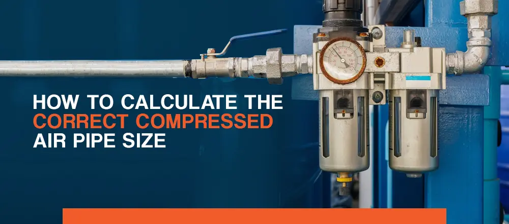
An air compressor can drastically reduce the time, coordination and stamina that have traditionally been required for a range of manual tasks. With an air compressor, you can link pneumatic tools to the unit and draw pressurized air for sawing, cutting, shearing, sanding and numerous other applications. However, these efforts would hardly be effective without sufficient piping. The following article covers how to determine what size pipe you need for a compressed air system.
Contact Us Find a Dealer Near You
Why Does Compressed Air Pipe Sizing Matter?
Pipe size is essential for supporting the appropriate air pressure. Without the correct size, the equipment may experience a large pressure decrease. A severe pressure decrease may require your compressor’s operating point to increase to compensate. This action consumes more electricity and, therefore, makes the compressor more expensive to use.
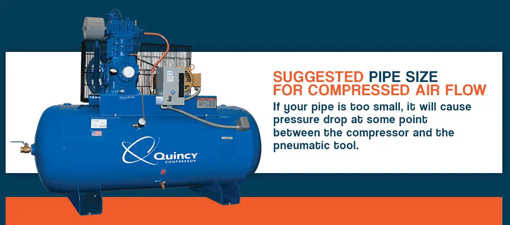
Pipe sizing must be exact, as pipes that are too small or large can cause many issues for your air compressor. If your pipe is too small, it will cause a pressure drop at some point between the compressor and the pneumatic tool due to friction with the pipeline. The problem comes down to the air pressure, which gets choked inside pipes that are too narrow to facilitate the flow of pressure. Pressure is also lost between the compressed air and pipe terminals if the piping has several connectors and twists. If the pipe lacks enough diameter to let the airflow through at the speed required for the application at hand, the system is forced to add excess pressure to the operation.
For example, if you try to get 100 pounds per square inch (psi) to your endpoint application, yet doing so requires 125 psi from your air compressor, your system will use an additional 25 psi just to yield sufficient pressure to the pneumatic tool or machine. On the other hand, if your pipe is thick enough to handle the required pressure, you could save the energy that would otherwise get consumed by the additional psi.
If your pipe is too large, it may indicate a poor financial investment, though it does not necessarily affect overall performance. Since large compressed air pipelines require more resources and money to construct and operate than appropriately sized pipelines, your company may lose money.
However, large pipelines may be a sound investment if your performance will increase in the future to compensate for the size difference. If your company plans to expand its operations in the coming years, installing larger pipelines now may be more profitable than removing your existing pipe network and installing a new system later.
For air storage considerations, pipe networks that are too large are not the ideal solution. While larger pipelines retain more air, they do not present a practical storage method.
Factors That Determine Sizing in Compressed Air Piping
For a compressed air system to have a healthy airflow, it’s essential to minimize pressure loss levels. If the system is specially designed for high-powered performance, pressure loss should be virtually nonexistent.

The required pipe size for an air compressor depends on two factors: the distance of the application and the volume of air being carried to the endpoint. If the pneumatic tools are located halfway across the factory floor, you will need a different pipe size than you would for an application three feet away from the air compressor. Likewise, the diameter of the pipe could differ if the application is high-intensity as opposed to low-intensity.
What Is the Best Pipe for Compressed Air?
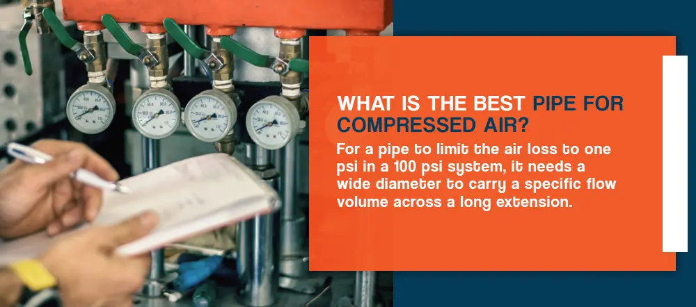
The ideal compressed air pipe size should not decrease the pressure by more than 1 psi. For a pipe to limit the air loss to 1 psi in a 100 psi system, it needs a wide diameter and a large enough surface area to carry a specific flow volume across a long extension. However, that same volume would not need as much diameter to travel a shorter distance.
You need to adjust the numbers according to the pressure of your compressor and the applications at hand. For example, if your system handles 120 psi, the pipe should be expected to carry more air at a 1% loss. Likewise, if the system only handles 80 psi, the pipe should be expected to carry lower volumes of air at a 1% loss.
It can be hard to determine the amount of airflow that will be sent through each arm of distribution in an air system because it depends on the application at hand. For certain applications, the air usage could flow at a normal, even rate. This rate tends to be the case in large systems such as heavy equipment consisting of various legs that each provide air to different machines and tools.
In smaller systems, a high surge or burst will often occur, especially if the air is sent to numerous applications at once. In cases where air is sent to multiple applications from a low-capacity air compressor, the surge is often followed by a period with no flow.
How to Size a Compressed Air Pipe
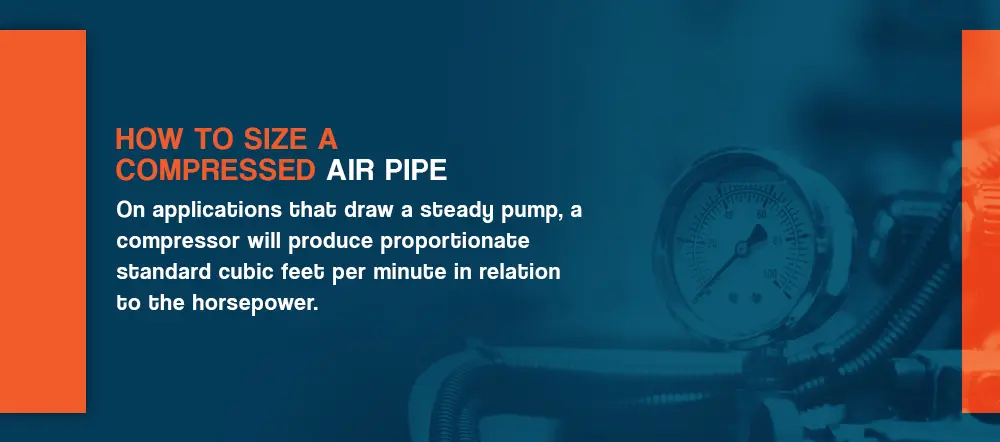
On applications that draw a steady pump, a compressor will produce proportionate standard cubic feet per minute in relation to the horsepower. If the compressor has high horsepower, it should produce a high rate of scfm.
On many systems, the pipe connected to the air compressor is selected to match the diameter of the outlet on the machine. While it may seem intuitive to correlate pipe diameter with outlet diameter, this can lead to errors within the system, such as drops in pressure and losses in efficiency.
For example, on a smaller air compressor, the user might opt to cut costs by placing a one-inch connection on an outlet to a 40 hp (30 kW) unit. The air compressor, when active, could develop pressure drop within the stretch of pipe inside the unit, yet this might not cause any problems when put through a test.
On applications that draw a steady pump, a compressor will produce proportionate standard cubic feet per minute (SCFM) in relation to the horsepower. If the compressor has high horsepower, it should produce a high rate of SCFM.
On many systems, the pipe connected to the air compressor is selected to match the diameter of the outlet on the machine. While it may seem intuitive to correlate pipe diameter with outlet diameter, this can lead to errors within the system, such as drops in pressure and losses in efficiency.
For example, on a smaller air compressor, the user might opt to cut costs by placing a one-inch connection on an outlet to a 40 horsepower (hp) — or 30 kilowatt (kW) — unit. The air compressor, when active, could develop a pressure drop within the stretch of pipe inside the unit, yet this might not cause any problems when put through a test.
Minimizing Pressure Drop in Compressed Air Pipe Systems
Pressure drop can be reduced by maintaining an appropriate air velocity for the application and choosing a smooth piping metal. With these measures, you can use a smaller size of pipe and still retain sufficient air velocity with minimal pressure drop.
The air velocity within a set of system pipes can range between 20 and 40 feet per second (ft/sec) — 20 ft/sec for compressor room piping, 30 ft/sec for plant distribution air mains, and 40 ft/sec for drops from mains to machinery. This way, any pressure drop that occurs will be kept at a minimum level.
For each unit length, pressure loss can be cut with smooth bore piping made of copper, aluminum, stainless steel or alloy steels. However, pressure loss could still occur if your piping system contains sharp turns of 90 degrees or more. If you have a complicated piping arrangement that consists of sharp turns, you should use larger pipes to minimize potential pressure loss.

How to Determine What Size Pipe You Need for Compressed Air
Calculating the correct pipe size for your compressed air system requires making careful calculations and understanding compressed air pipe size charts.
1. Determine the Equipment’s Lowest System Pressure
To know the necessary pipe size for your air compressor, you must also know the minimum operating pressure for the unit. This figure should be based on the minimum requirements specified by the manufacturer. Ideally, the distribution system of an air compressor will lose virtually no pressure between the connecting points of the unit and each pneumatic application.
For example, if your compressor has a peak pressure requirement of 95 psi — this being for an outlier application that commands more pressure than the rest — the minimum operating pressure for your system would be 98 psi, as this would be necessary to accommodate your highest usage level. Therefore, you would never want to run the system beyond 98 psi, as doing so would consume excessive amounts of energy.
2. Calculate the Maximum Cubic Feet per Minute Requirements
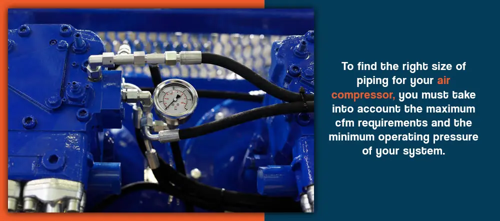
To find the right size of piping for your air compressor, you must take into account the maximum cubic feet per minute (cfm) requirements of your system. To make an accurate determination of the maximum cfm demands of your system, you would need to conduct a study.
Consider the worst possible scenario that could occur during a momentary usage cycle. Such use is usually accommodated with air storage at the point of use. Therefore, it is not necessary to change the pipes throughout your facility merely to accommodate instances of momentary use.
3. Consult a Compressed Air Pipe Size Chart
Any Google search on how to calculate the correct compressed air pipe size will bring up links to charts that show the ratings of a system’s cfm. These ratings are usually based on a system’s psi and the length of pipes that connect the machine to its endpoint applications. For aluminum pipe fittings, the flow charts that correlate to a particular make or size will be included with the product.
The trouble is these charts can be inconsistent, as some are based on outside diameter measurements, whereas others are based on inner diameter measurements. Understanding which diameter measurement the chart is based on is essential. You will also need to know the minimum operating pressure, maximum cfm, and the piping diagram and its joints.
Design Elements in a Compressed Air Pipe Network
When developing and designing your compressed air system, the first step is to create a network design, which is an inventory list detailing the pneumatic system consumption and a graphic illustrating the locations of the various components.
The essential parts of a compressed air network include the air compressor and risers. The compression plant transports the compressed air through the risers to the consuming location. During circulation, the pipelines separate the air, routing it from the distribution system to its final destination.
A mistake that some users make is to simply assume that energy lost due to over-pressurization is merely collateral for the occasional high-pressure application. The fact is, this is the performance and longevity of your compressed air system at stake. The price that you might pay to upgrade your piping with sufficient measurements could be just a drop in the bucket compared to the price you might pay on an annual basis for wasted energy and lost air power.
If you wish to have pipes that will accommodate all possible pressure demands, consider the layout of your system. While it might seem useful to purchase the largest pipes possible, this setup could be a waste of money for excessive piping. Instead, consider the placement of an adequate set of pipes in relation to your compressor and air tools. The only real reason to incorporate oversized pipes into your current system is if you intend to enlarge your equipment to a size requiring such pipes in the near future.
For example, 500 feet of piping with a one-inch width would roughly equal 18 gallons of storage. Likewise, 500 feet of piping with a two-inch width would roughly equal 18 gallons of storage. Between the two, you would gain 59 gallons of storage quantity that may be of no use to your applications, yet pay a much higher price in the process.
Correct Compressed Air Pipe Size for Specific Applications
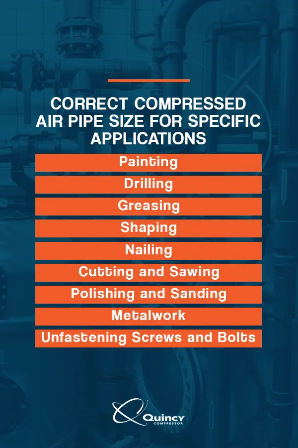
With a reciprocating or rotary screw air compressor, you can accomplish tasks provided you have the proper tools and an optimal connection. For most single applications, you would only need a fraction of the 100 psi capacity of an air compressor. As long as the pipe is under 100 feet in length, you will only need a half-inch diameter to facilitate the air velocity and pressure required for the following applications:
Painting
A half-inch pipe of varying length will allow you to paint any surface to perfection with a pneumatic paintbrush, which typically requires between 3 and 11.3 cfm at 90 psi. With an air-powered brush, you can paint houses, vehicles, furnishings and appliances in just a fraction of the time it would take with manual brushes and rollers. Best of all, the job can be accomplished free of streaks, bubbles and inconsistency.
Drilling
If you perform drilling tasks, as little as 3 cfm at 90 psi and a half-inch pipe could have you operating a pneumatic drill. Unlike manual drills, the air-powered equivalent can drill holes through the hardest woods and surfaces in a split second. Whether you need to create six or 12 uniform holes for the purpose of assembly, anywhere from 3 to 6 cfm will give you enough power to complete the task in under a minute, regardless of the length of your pipe.
Greasing
If you perform auto maintenance and repair work, a pneumatic greaser can ease up and facilitate one of the grimiest yet necessary tasks involved with engine upkeep. With as little as 4 cfm at 90 psi and a half-inch pipe, you could use an air-powered greaser gun to neatly and evenly lubricate all the moving metal parts in the engine sinks of cars, vans, trucks and SUVs.
Shaping
If you work with metals or do repair work on automobiles, a pneumatic angle grinder would be the go-to tool for applications such as cutting and buffing. Depending on the surface at hand, you might even use the tool to sand surfaces and polish edges. A standard angle grinder will require between 5 and 8 cfm, necessitating a half-inch piping diameter at any length.
Nailing
For the types of pneumatic applications that you would need for renovation work, one of the handiest tools is an air-powered nailer. As long as you have at least 0.3 cfm coming from your air compressor and a half-inch pipe to connect the tool, you can nail boards and shelves into place in a matter of seconds, as opposed to the minutes it would take with a hammer.
Nailing the frame of a house into shape is a lot different than nailing the back of a drawer into place. For the former task, you could have multiple nails fastened into place within seconds with a pneumatic frame nailer, which can run with as little as 2.2 cfm and a half-inch pipe. A frame nailer operates similarly to a gun in that you load the nailer with a cartridge of nails. Instead of nailing one nail at a time, you point the frame nailer along specified points up and down a given board and, within seconds, can have it nailed at 12 different spots.
Cutting and Sawing
Some of the more intensive metalworking applications require tools that run on higher volumes of airpower. One such tool is the pneumatic metal cutter, which can be used to slice thicker panels of metal as if they were paper. An air-powered metal cutter can do this work with as little as 4 cfm at 90 psi and a half-inch pipe.
Another task that requires high levels of manual exertion is sawing, which can be a physically draining task if done the old-fashioned way. Thankfully, most of the exertion is removed from the task when you use an air-powered saw, which can operate on as little as 5 cfm at 90 psi with a half-inch pipe. Unlike regular saws, pneumatic saws can cut through metal as well as wood.
Polishing and Sanding
In the old days, one of the most exhausting manual applications in woodwork and finishing was the task of sanding surfaces. Today, all you need is between 11 and 13 cfm at 90 psi and a half-inch pipe to operate an air-powered sander, which can finish off surfaces with a smoother and more even finish than you could ever get from doing things the old-fashioned way.
Hard materials call for high-powered tools, but it only takes between 4 and 6 cfm at 90 psi to polish metal, rock and wood when you have a mini die grinder. With the tool in hand, you can instantly polish metal fixtures, coins and antiques into a newly shined and buffered finish. You can even use a die grinder to carve and stencil hard materials with maximum performance from a half-inch pipe of any length.
Metalwork
One of the more demanding air-powered applications is metalwork, which you can do with handled pneumatic tools provided you have sufficient air power and velocity to power your operations. With as little as 3 cfm at 90 psi and a half-inch pipe, you could activate a pneumatic chisel and use it to slice metal sheets and also carve shapes out of wood, rock and other hard materials.
If you do more detailed work with metals, one of the handiest tools in your arsenal could be a pneumatic metal nibbler, which you can operate with 4 cfm at 90 psi and a half-inch pipe. With an air-powered nibbler, you can shape metal sheets into fixtures, frames, ornaments and wall hangings. A pneumatic nibbler can cut through metal like scissors through paper.
For some of the more demanding applications in metalwork, you will need a pneumatic shearing tool for the tasks at hand. A shear will require anywhere from 8 to 16 cfm at 90 psi through a half-inch pipe. If the pipe exceeds 100 feet in length, you will need a 3/4-inch pipe to accommodate the pressure and velocity of applications that exceed 15 cfm. With that power, the shear will allow you to make numerous cuts per minute through thick gauges of sheet metal and aluminum for furnishings and appliances.
Unfastening Screws and Bolts
Some of the most stubborn tasks involve jammed fasteners that refuse to come undone with reverse motions and regular tools. In automobile engines, for example, you will sometimes encounter bolts that refuse to dislodge no matter how hard you try. However, with an air-powered socket wrench, it only takes between 2.5 and 5 cfm at 90 psi and a half-inch pipe to unfasten bolts from the toughest spots.
Whether you work on cars or appliances, one of the most powerful tools that you could have at your disposal is a pneumatic wrench, which can be used to screw and unscrew fasteners in some of the most hard-to-reach spots. Even if a fastener has rusted into place and has not been unfastened for decades, an air-powered wrench will usually dislodge the screw in a matter of seconds, all with anywhere from 2.5 to 10 cfm at 90 psi with a half-inch pipe.
Get the Right Pipe Size From Quincy Compressor
Regardless of the application at hand, it is important to know what size of piping your compressed air system needs to meet a given set of demands. Whether you operate a workshop or run a pressing plant, it is crucial to have a compressor that can power all of your tools and also to have the right pipes to facilitate the pressure and air velocity.
For almost a century, Quincy Compressor has been the leading innovator in compressed air technology. Many of the furnishings and automobiles that you see from day to day have been assembled with pneumatic tools powered by compressors sold in the Quincy catalog. Explore our piping to create an efficient compressed air pipe network for your operations, or contact us online to learn how to upgrade your system with an optimal piping setup.
Contact Us Find a Dealer Near You
Last Updated on October 13, 2023 at 1:17 AM
Table of Contents
- Why Does Compressed Air Pipe Sizing Matter?
- Factors That Determine Sizing in Compressed Air Piping
- What Is the Best Pipe for Compressed Air?
- How to Size a Compressed Air Pipe
- Minimizing Pressure Drop in Compressed Air Pipe Systems
- How to Determine What Size Pipe You Need for Compressed Air
- Design Elements in a Compressed Air Pipe Network
- Correct Compressed Air Pipe Size for Specific Applications
- Get the Right Pipe Size From Quincy Compressor